Pump Performance Curves and Engine Selection
[kadence_subtitle]
I. Unveiling the Intricacies of Pump Performance Curves
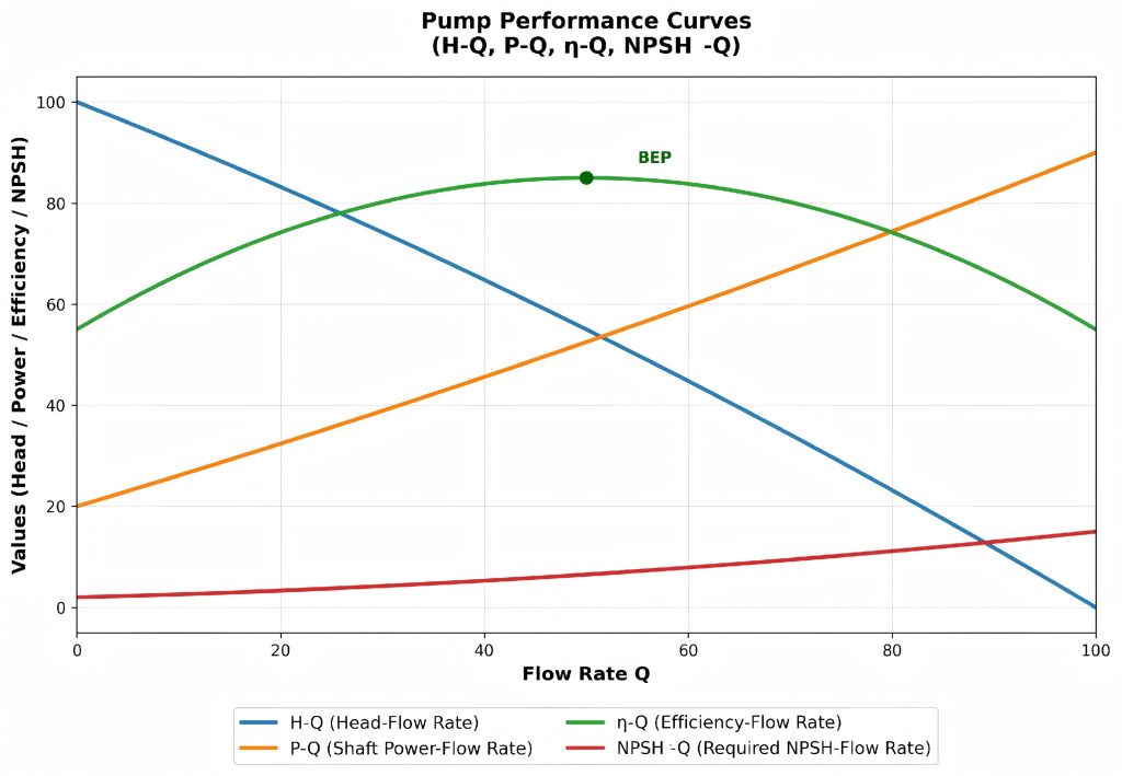
Pump performance curves, often referred to as operating curves, are the cornerstone of understanding a pump’s behavior under diverse operating conditions. These curves provide a comprehensive graphical representation of the relationships between various performance parameters, offering invaluable insights for efficient pump operation and system design. The following are the key curves that constitute a pump’s performance profile.

1. H – Q Curve (Head – Flow Rate Curve)
The H – Q curve is the linchpin of pump performance, depicting the head (H) that a pump can generate at different flow rates (Q). Characteristically, it is a downward – sloping curve, signifying an inverse relationship between head and flow rate. As the flow rate increases, the head provided by the pump gradually decreases. This fundamental curve serves as a crucial reference for engineers and operators, enabling them to anticipate the pump’s performance in different scenarios and make informed decisions regarding system design and operation.
2. P – Q Curve (Shaft Power – Flow Rate Curve)
The P – Q curve showcases the drive power required by the pump at varying flow rates. Typically, this curve demonstrates an upward trend, indicating that the power demand of the pump increases as the flow rate rises. Understanding this curve is essential for the proper selection of drive equipment, such as motors or engines. By accurately assessing the power requirements at different flow rates, one can ensure that the chosen drive system can adequately meet the pump’s energy demands, preventing issues such as overheating and premature wear.
3. η – Q Curve (Efficiency – Flow Rate Curve)
The η – Q curve illustrates the pump’s efficiency at different flow rates. It typically assumes a bell – shaped form, with an optimal efficiency point (BEP) at its apex. Operating the pump as close as possible to the BEP is a primary objective in system design, as it maximizes energy efficiency and minimizes operational costs. Deviating significantly from the BEP can lead to reduced efficiency, increased energy consumption, and potential damage to the pump.
4. NPSH – Q Curve (Net Positive Suction Head – Flow Rate Curve)
The NPSH – Q curve indicates the minimum net positive suction head (NPSHr) required by the pump at different flow rates. Cavitation, a detrimental phenomenon that can cause severe damage to pump components, occurs when the NPSH available in the system falls below the NPSHr. By referring to this curve, engineers can ensure that the system is designed to provide sufficient NPSH, thereby preventing cavitation and ensuring the reliable and long – term operation of the pump.
II. Navigating the Selection Process for Pump Engines
The selection of an appropriate engine for a pump is a critical decision that can significantly impact the pump’s performance, reliability, and overall cost – effectiveness. The following principles should be adhered to during the engine selection process:
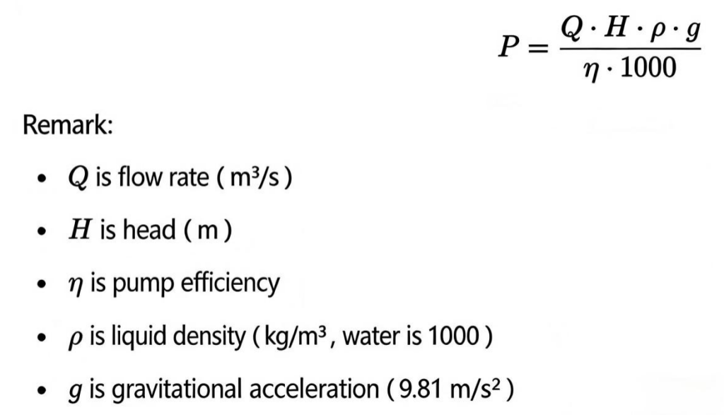
1. Determining the Pump’s Shaft Power Requirement
The first step in engine selection is to precisely determine the pump’s shaft power requirement. By referring to the pump’s performance curve, the required shaft power (P) at the design flow rate and head can be accurately identified. This value serves as the baseline for subsequent engine selection steps.
2. Selecting the Engine’s Rated Power
To ensure reliable operation, the engine’s rated power should be selected to exceed the pump’s required power by a certain margin. This is achieved by multiplying the pump’s required power by a safety factor. The safety factor typically ranges from 1.1 to 1.3, depending on the specific application and operating conditions. For instance, if a pump demands 100 kW of power, the selected engine power should fall within
3. Ensuring Engine Speed Matching
Pumps are designed to operate at specific speeds, such as 1450 rpm or 2900 rpm. It is essential that the engine’s output speed either directly matches the pump’s required speed or can be adjusted to the appropriate speed through the use of a reduction gear, such as a gearbox or pulley. Proper speed matching is crucial for maintaining the pump’s performance and preventing mechanical failures.
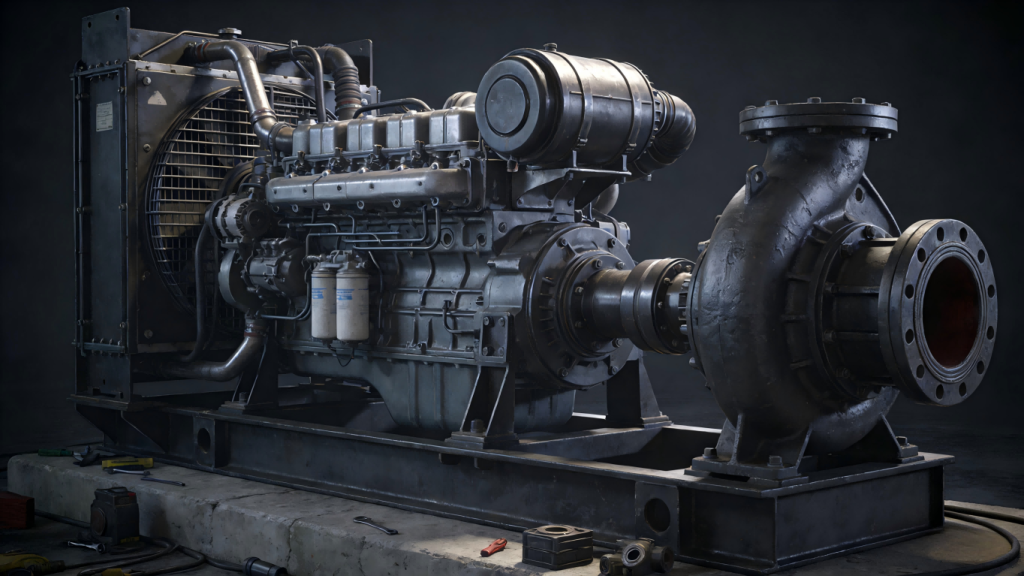
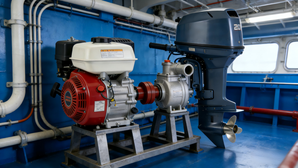
4. Considering Fuel Type and Environmental Adaptability
The choice of fuel type is an important consideration, as it can influence the pump’s suitability for different operating environments. Diesel engines are a popular choice for pumps, especially in fieldwork applications or areas where access to electricity is limited. They offer high power density and the ability to operate independently. On the other hand, electric pumps are well – suited for fixed operating conditions in locations with a reliable power supply. Additionally, it is vital to account for the impact of environmental factors such as temperature, humidity, and altitude on the engine’s power output.
5. Evaluating Starting Performance and Load Response
The engine should possess excellent starting and acceleration performance to meet the pump’s requirements for rapid start – up and short – term overload operation. A well – performing engine can quickly reach the required operating speed and respond effectively to sudden changes in load, ensuring smooth and efficient pump operation.
III. A Concise Overview of the Selection Process
1.Define the Pump’s Operating Parameters: Clearly establish the pump’s design flow rate, head, efficiency, and other relevant parameters. These parameters form the basis for all subsequent selection decisions.
2.Consult the Pump Curves: Utilize the pump performance curves to determine the power requirement at the maximum operating point. This step is crucial for accurately sizing the engine.
3.Select the Engine Type: Choose the most appropriate engine type, such as a diesel engine or an electric motor, based on factors such as power requirements, operating environment, and fuel availability.
4.Confirm Speed Matching: Ensure that the engine’s output speed is compatible with the pump’s required speed, either through direct matching or the use of a suitable speed – reduction mechanism.
5.Account for Environmental Conditions and Safety Margins: Consider the impact of environmental factors on the engine’s performance and incorporate an adequate safety margin to ensure reliable operation.
6.Final Confirmation: Verify that the selected engine meets all performance requirements, is cost – effective, and is easy to operate and maintain. This comprehensive evaluation ensures the long – term success of the pump – engine system.