The main causes of mechanical seal leakage and the way to extend the service life of mechanical seals
[kadence_subtitle]
Ⅰ.The main causes of mechanical seal leakage
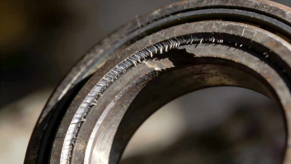
1. Wear on the end faces of the dynamic and static rings leads to mechanical seal leakage.
2. Unstable process conditions and improper installation led to mechanical seal leakage.
① Mechanical seals fail due to fluctuations in operating conditions (vibration, cavitation, etc.) or inadequate flushing, leading to disruption of the lubricating film, dry friction, and high temperatures. This ultimately results in failure through thermal shock fracture and material carbonization wear.
② When the pump is idling, the mechanical seal experiences dry friction due to the lack of material lubrication on the sealing surface. This causes a sudden temperature rise, exceeding the O-ring’s temperature limit and causing it to burn out. This, in turn, leads to loosening and detachment of the stationary ring, which is eventually shattered during high-speed rotation.
3. Mechanical seal ring failure can also cause leakage.
Misalignment of the dynamic and static ring seals; insufficient surface finish of the shaft or bushing that mates with the seals; or excessively small mating dimensions; physical or chemical reactions between the seals and the sealing medium, corrosion, deformation, aging, etc., can all lead to leakage.
4. Improper assembly leads to mechanical seal leakage.
Premature failure of mechanical seals can be caused by several factors, including: unclean mechanical seal components before assembly; damage or scratches to components; improper assembly; misaligned springs; loose fastening screws; and damage during disassembly.
5. Improper selection and design lead to mechanical seal leakage.
Due to the diverse characteristics of process media in chemical plants, improper design and selection of mechanical seals, such as excessively low or high specific pressure at the sealing end face or high cold shrinkage of the sealing material, can easily lead to mechanical seal failure and leakage.
Ⅱ. Solutions
(Ⅰ) Correct selection of mechanical seals
We must provide mechanical seal manufacturers with detailed process parameters and technical requirements for equipment operation to avoid reducing the service life of the selected mechanical seal due to its unsuitability for the on-site working conditions.
(Ⅱ) Proper installation and assembly (manufacturing standards)
1. Spring compression
The spring compression determines the specific pressure at the mechanical seal end face and must be controlled within a given range (typically 3-6 kg/cm²). During installation, the compression dimension of the spring after installation should be calculated according to the parameters provided by the manufacturer using the formula B=A-P/k, and then precisely adjusted to the target value by increasing or decreasing the thickness of the adjusting shim to ensure sealing performance and service life.
2. Dynamic ring seal tightness
The hazards of over-tightening the dynamic ring seal mainly include accelerated wear, increased movement resistance, spring overload, and seal deformation. To ensure the floating property of the dynamic ring, its inner diameter should be 0.5–1 mm larger than the shaft diameter to compensate for vibration and misalignment. However, excessive clearance can easily cause the seal to jam. During installation, the tightness should be determined by whether it can be pressed in by hand after applying lubricant.
3. Stationary ring seal tightness
Over-tightening the stationary ring seal can lead to deformation, breakage, and difficulty in disassembly and assembly. Therefore, its inner diameter is usually 1-2 mm larger than the shaft diameter. The tightness of the installation should be controlled so that it can be pressed in by hand after applying lubricant—if it can be easily pressed in by hand, it is too loose; if it cannot be pressed in by force, it is too tight.
4. Mechanical seal manufacturing and installation requirements
(1) Three core requirements are set for shafts (or bushings) with mechanical seals installed: radial runout tolerance must meet the specifications, surface roughness Ra ≤ 3.2μm, and outer diameter tolerance h6. Simultaneously, the axial movement of the rotor during operation should be ≤ 0.3mm, and the runout tolerance of the locating end face of the sealing cavity and end cover on the shaft surface must also meet the corresponding standards.
(2) The rotating ring auxiliary seal is installed at the end of the shaft (or bushing).
(3) The sealing parts, shaft surface and sealing cavity must be cleaned thoroughly, and the flushing fluid pipeline of the sealing end face must be unobstructed.
(4) Before installation, confirm that the product model and specifications are consistent with the equipment requirements. When the temperature of the conveyed medium is too high or too low, or when there are impurities, flammable, explosive or toxic particles, corresponding measures such as sealing, flushing, cooling and filtration must be taken.
(5) Apply oil evenly to the contact points between the sealing shaft, cavity and gland and the auxiliary sealing ring (Note: For ethylene propylene rubber or in cases where the medium does not allow the injection of lubricating oil, vegetable oil or soapy water can be applied).
(6) When installing the sealing ring, it is not allowed to apply grease to the sealing ring. Otherwise, the sealing ring will swell and become larger, causing the mechanical seal to leak.
(7) Check the sealing installation dimensions during installation. The maximum allowable tolerance for the axial installation dimensions of a single spring seal is 1.0 mm, and for a multi-spring seal it is ±0.5 mm.
(8) Install the mechanical seal sleeve on the shaft at the designed working height.
(9) The through hole is tightened diagonally, and the bolts are used to tighten the entire seal to the sealing cavity (pump cover).
(10) When the seal is equipped with an auxiliary system, the pipeline is connected correctly according to the markings.
5. Installation of cartridge mechanical seals
For cartridge mechanical seals, the mechanical seal compression has been adjusted and mechanical operation tests have been conducted at the factory. Therefore, it is not allowed to disassemble the mechanical seal or readjust the mechanical seal compression during our on-site installation.
6. Installation of bellows mechanical seal
Before installing a bellows mechanical seal, the bellows should be checked for leaks using kerosene. Installation can only proceed if the bellows is confirmed to be intact and leak-free. Furthermore, because the bellows of a bellows mechanical seal are easily damaged, extreme care must be taken during installation.
(Ⅲ)Proper Process Maintenance
1. Strict Control of Process Operations and Indicators
To prevent mechanical seal failure due to overheating or other reasons, lubrication and heat dissipation conditions should be improved by adjusting the flow rate, avoiding abnormal pump operating conditions (such as surge or cavitation), and strengthening flushing and cooling (including filtering impurities, selecting appropriate flushing methods, increasing flushing flow rate, and maintaining stable supply), thereby extending service life.
2. Replacement of New and Old Seals
A new mechanical seal is not necessarily superior to an old one; its effectiveness depends on quality, material selection, and dimensional accuracy. In polymerizing and deep-penetrating media, if the stationary ring is not excessively worn (e.g., cracks, penetrating scratches), replacement is not advisable, as the deposits formed over a long period of stagnation already provide a good seal.
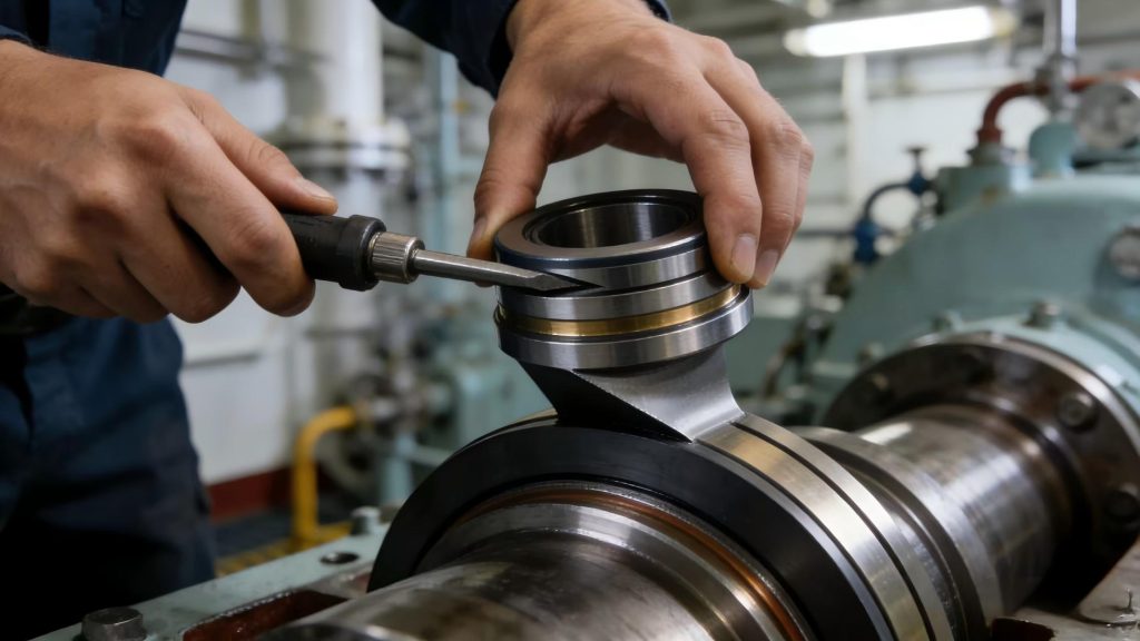
3. Do not rush to disassemble and repair if leakage occurs.
Conclusion
As long as the installation, maintenance, and use of the mechanical seal are strictly performed according to the technical requirements, a good sealing effect can be achieved, and the service life of the mechanical seal will be greatly extended.