
Basic Design Specifications for Generator Sets
[kadence_subtitle]
1. Static and Dynamic Loads
Static loads are calculated based on the operating weight of the generator set. The operating weight is the dry weight of the generator set plus the weight of the cooling water and lubricating oil. While the volume of oil and water varies by model, for units that often weigh several or even dozens of tons, an estimate of 300 kg/MW is generally acceptable when precise values are not required.
For the vast majority of models and applications, vibration isolators can reduce vibration by more than 90%. Taking into account the unit’s short-circuit current, the dynamic load for different units is generally 1.3 to 1.5 times the static load.
When multiple generator sets operate in islanded parallel mode, phase imbalance may occur; in such cases, dynamic loads must be calculated as twice the static load.
Calculating dynamic loads requires detailed parameters of the generator set; for accurate calculations, consult the relevant generator set manufacturer.
2. Length and Width
For the generator set itself, the length and width of the foundation should be slightly larger than the generator set’s steel frame base. Generally, an additional 300 mm in both the length and width directions is required to facilitate the installation of vibration dampers.
For containerized or soundproofed units, the foundation’s length and width should be slightly larger than the external dimensions of the container or soundproof enclosure to facilitate positioning and securing the unit. However, to ensure convenient access for personnel (and to avoid an awkwardly sized step), it is not recommended to increase the dimensions excessively; an increase of approximately 100 mm is appropriate.
3. Thickness
The thickness of the generator set foundation is calculated using the following formula. Generally, the generator set weight can be taken as 1.3 to 1.5 times the actual weight; adjust accordingly for special cases.
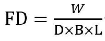
FD = Foundation thickness (m)
W = [Operating weight of the generator set + other equipment (e.g., container, auxiliary equipment, etc.)] × 1.5 (kg)
D = Concrete density (kg/m³) (2400 for C20 concrete)
B = Foundation width (m)
L = Foundation length (m)
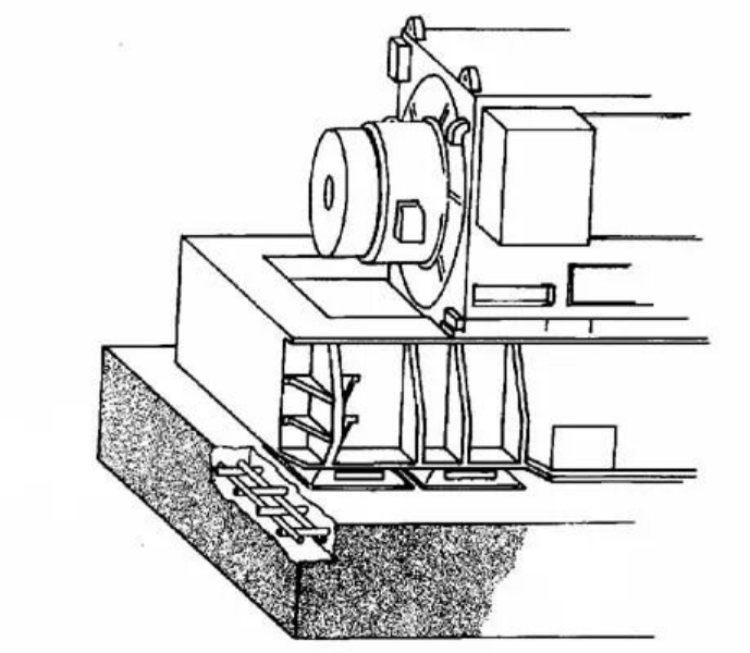
It is recommended to use concrete with a 28-day compressive strength of no less than 20 MPa (C20), with φ14 rebar, and a horizontal and vertical reinforcement spacing of 150 mm. A double-layer rebar mesh structure should be used, with the rebar positioned at least 75 mm from the base surface.
4. Height
Provided the load-bearing requirements are met, the generator set foundation may be either elevated above ground level or flush with the ground. It is common practice to elevate the foundation 100–300 mm above ground level. This approach facilitates construction alignment and drainage, while also visually indicating that “this is a generator set unit.”
5. Vibration Dampers
Most generator sets rest on the ground via vibration isolators. To ensure the generator set’s steel foundation remains level, the isolators are designed with a certain degree of height adjustment capability.
Caterpillar G3500 series models have a shock absorber adjustment range of ±3 mm;
The Mannheim full series (including Caterpillar CG series models) has an adjustment range of ±2 mm;
The entire Yambach series uses two long strips of Celoma rubber pads, relying on the rubber’s elasticity for passive adjustment.
Vibration dampers for other brands generally fall into these categories or their variations—such as slight adjustments to spring structures or the use of smaller rubber pads—with similarly limited adjustment ranges. Some low-power models lack vibration damping devices and are rigidly connected to the ground; for these models, dynamic loads must be increased by approximately three times, and requirements for ground levelness and mounting methods vary, which will not be elaborated upon in this article.
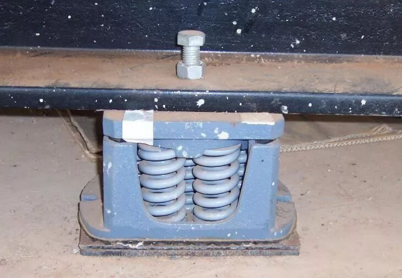
Caterpillar G3500 Series Generator Set Vibration Dampers
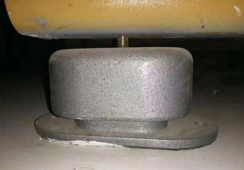
Mannheim generator set vibration dampers (not yet fully installed)
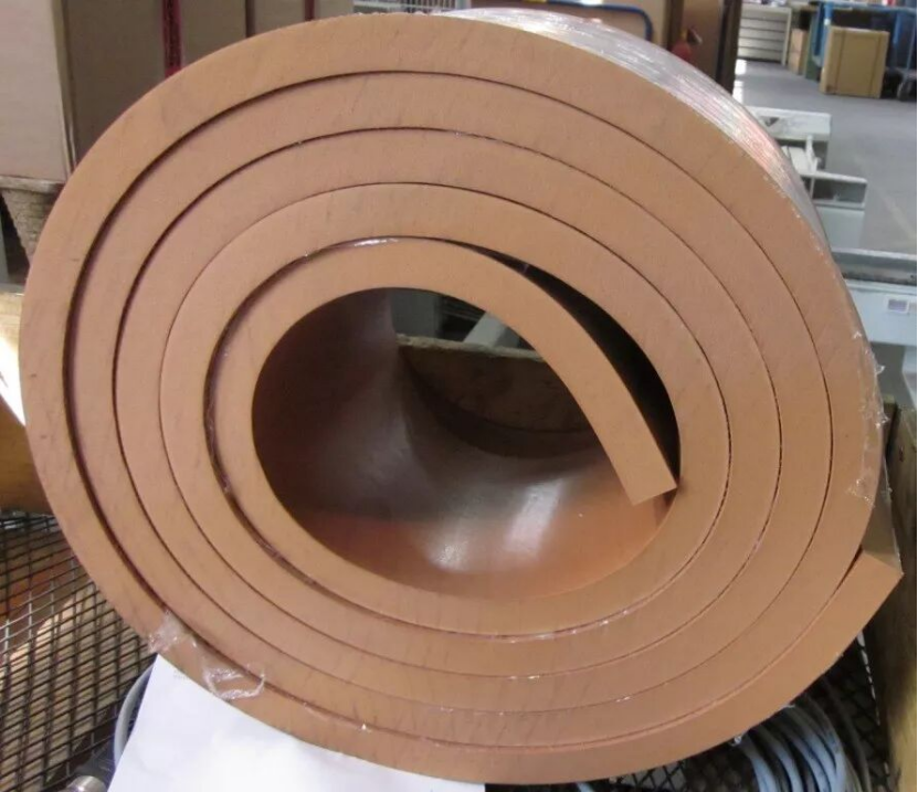
Yanmar Unit Vibration Dampers
For grid-connected units, no anchor bolts are required to secure the vibration isolators to the ground.
For units operating in islanded parallel mode, it is recommended to secure the vibration isolators to the ground with anchor bolts.
6. Levelness
The flatness of the foundation is strictly required for all areas where the vibration isolators contact the ground (for Yambach or other units using vibration isolation pads, this refers to the area where the pads are laid). The flatness requirement within this area is the same as the adjustment capacity of the vibration isolators, i.e., the height difference between the highest and lowest points must be:
Caterpillar G3500 series: ±3 mm;
Mannheim (including Caterpillar CG series): ±2 mm;
Yanbach: ±1.5 mm.
Imported units generally have higher requirements for foundation flatness. If the required flatness cannot be achieved with a single pour, water grinding can be used to further improve flatness, or embedded steel plates can be added at the shock absorber locations to adjust the flatness. In the image of the Caterpillar shock absorbers above, the flatness was adjusted using steel plates.
Failure to meet flatness standards may not reveal immediate issues, but it can lead to a series of chronic problems, such as increased vibration, higher failure rates, and even accelerated crankshaft wear, thereby shortening the unit’s service life. Therefore, strict adherence to foundation flatness requirements is essential during installation.
7. Vibration and Resonance
The mechanical structure of internal combustion engines is relatively complex, with numerous vibration sources. In the low-frequency range (25 Hz–300 Hz), vibrations primarily originate from mechanical components such as piston knocking, cam mechanisms, and gear trains, while higher-frequency vibrations are mainly caused by combustion-induced excitation.
Generator sets are separated from the ground by vibration isolators, which can reduce vibrations by 90%–98%. Their natural frequency generally ranges between 3–6 Hz, which avoids the natural frequencies of most buildings. Given the complexity of a building’s natural frequencies, if resonance is a concern, the building can be measured for the specific project. Accurate data on the natural frequency of the vibration isolators can be obtained from the generator set manufacturer.
In vibration-sensitive environments, vibration transmission can be further prevented by adding damping pads or filling the foundation with sand.
8. Embedded Steel Plates and Cutouts
It is often necessary to embed numerous steel plates in the foundation. These embedded steel plates fall into two main categories: first, the leveling base mentioned earlier; second, equipment positioning, such as soundproof enclosures and water pumps. The location and quantity of embedded steel plates must be determined based on the actual equipment requirements.
Another type of embedded component is conduit. To maintain a cleaner site appearance, some conduits allow cables to run directly underground into cable trenches; the placement of conduits should also be determined based on actual conditions.
Cable trenches and conduit trenches are typically routed to avoid equipment foundations; however, if necessary, they may be installed in non-load-bearing areas of the foundation.
9. Drainage
Water and oil leaks are inevitable during generator set operation, and there is also the possibility of using water to rinse the floor. Therefore, areas of the foundation where flatness is not required (such as the center of the foundation) should be designed with a slight slope and drainage channels connected to the drainage trench. This will facilitate drainage and help maintain the cleanliness of the facility.