What is meaning of steel marked symbols A, B, C, and D on propellers?
[kadence_subtitle]
The A, B, C, and D markings on the body of propeller blades are key technical symbols which indicates permeate the entire process of propeller design, production, assembly, and maintenance. Their specific meanings and functions are further refined depending on the propeller structure type (integral welded or split type). The core logic revolves around three dimensions: pitch matching, installation positioning, and quality control, as detailed below:
I. Core function 1: Pitch Series Code (Industry-wide Standard)
Applicable to both integral welded propellers and split propellers. It’s the core function of the A, B, C, D markings.
Definitions and Classification Rules
1. Based on the ship’s design speed and main engine power requirements, different pitch grades are classified.
2. Grades are identified by the letters A, B, C, and D in that order.
3. Pitch values increase in the order of A → B → C → D.
Applications and Functions
Applications:
A Series (Small Pitch): Low-power main engines, low-speed inland waterway vessels, and economical speed conditions for ocean-going vessels.
B/C Series (Medium Pitch): Medium-power main engines, coastal transport vessels, bulk carriers, container ships, and other conventional merchant ships.
D Series (Large Pitch): High-power main engines, high-speed vessels (such as Ro-Ro ships and luxury cruise ships), and heavy-load navigation conditions.
Functions:
A Series (Small Pitch): Reduces main engine load, avoids power waste, improves anti-cavitation performance, and extends service life.
B/C Series (Medium Pitch): Balances speed and fuel economy.
D Series (Large Pitch): Fully utilizes main engine power, converting more power into thrust to meet high-speed navigation requirements.
Structural Adaptation Details
Integral Welded Propeller:
Features: The blades and hub are welded together as a single structure; the pitch is determined by molds before leaving the factory.
Markings: A-D are directly marked on the blade body, serving as the core basis for acceptance and assembly.
Function: Ensures precise matching between the propeller and the ship’s propulsion system.
Split Propeller:
Features: The blades can be disassembled and replaced individually.
Markings: A-D are marked simultaneously on both the blade and hub mounting positions.
Function: Ensures consistent propulsion system performance.
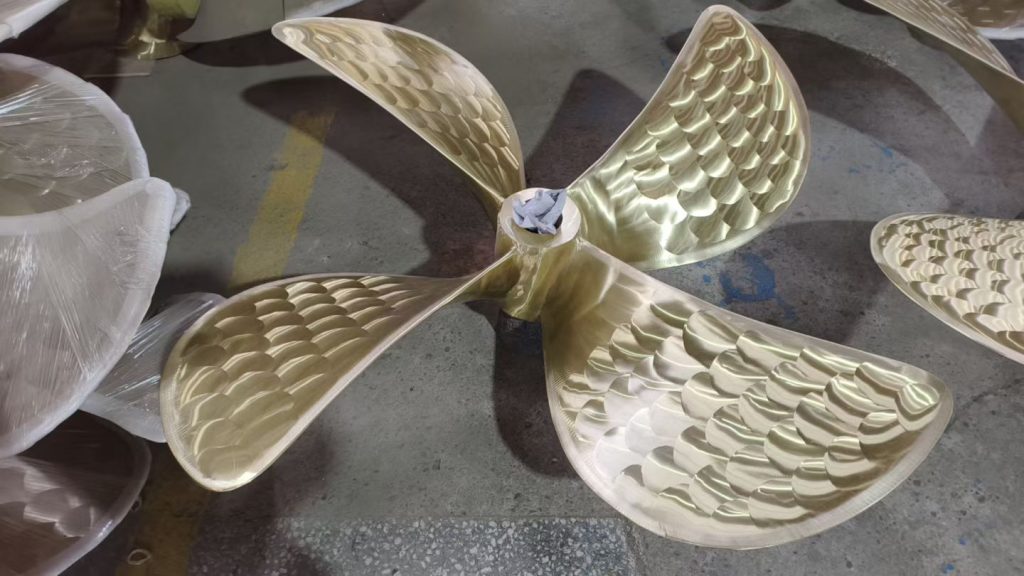
II. Core function 2: Blade numbering for multi-bladed propellers (specifically for four-bladed propellers) Applicable to both integral welded and split structures, its core function is to ensure the dynamic balance accuracy and thrust uniformity of the propeller.
Numbering Rules and Processing Requirements
1. The manufacturer will use A, B, C, and D to mark the four blades respectively; the numbering is determined during the propeller casting or welding stage; the number corresponds to the installation phase angle of each blade.
2. During processing, based on the numbering, the airfoil, thickness, and weight of each blade are precisely adjusted to ensure that the mass deviation of the four blades is controlled within 0.5%, meeting the dynamic balance standard.
The technical value of assembly and maintenance
When assembling propellers, split-type propellers must be assembled strictly according to the blade numbers and hub mounting positions to prevent damage to the main unit and shaft system from rotational vibration. For integral welded propellers, the blade numbers are used as a reference to ensure the coaxiality of the propeller and shaft system.
When maintaining propellers, technicians can quickly locate blades that need polishing, welding repair, or replacement based on the propeller numbers. They can also trace the blade processing batch and flaw detection records through the propeller numbers. After repair, the propeller must be re-balanced based on the numbers to ensure that the propeller vibration value meets the standards.

III. Supplementary function: Quality Traceability Labels ( only a few manufacturers uses it)
Some propeller manufacturers use A, B, C, and D as quality traceability identifiers for all types of propellers, enabling quality control throughout the propeller’s entire lifecycle. This identifier traces the material batch of the cast steel for the propeller blades, the welding process batch for integrally welded propellers, and the non-destructive testing level of the propeller blades. This provides data support for ship operators during annual propeller maintenance or troubleshooting, and also helps propeller manufacturers quickly find suitable repair solutions during after-sales maintenance.
IV. Key Considerations
Different propeller manufacturers may vary different propeller marking specifications; their meanings should be verified against the propeller manufacturer’s technical manual. During propeller assembly and maintenance, the technical requirements for propeller markings must be strictly followed to avoid misinterpretation affecting propeller propulsion efficiency or causing equipment malfunction. For propellers on ocean-going vessels, it is recommended to check and record the propeller’s A-D markings during each dry-docking overhaul and include them in the propeller equipment management file for long-term tracking of propeller performance changes.